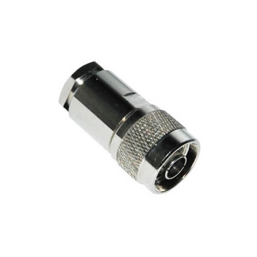
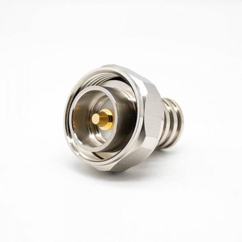
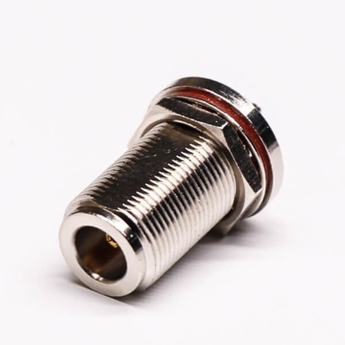
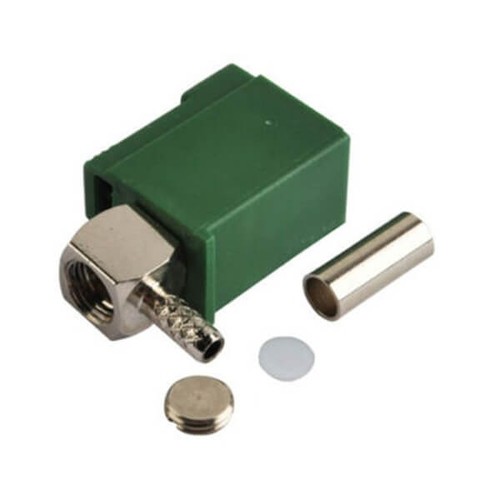
About N Type Connector
Techinial Datasheet:
Electrical Characteristics
- Impedance 50 ohm
- Frequency Range: 0-11 Ghz
- VSWR: Straight type 1.3max / R/A type 1.5max
- Dielectric Withstanding Voltage: 2500 V rms
- Working Voltage: 1000 V rms
- Center Contact Resistance 1.0 m (Milliohms max.)
- Outer Contact Resistance 0.2 m (Milliohms max.)
- Insultation Resistance 5 x 10³ m (Megohms min.)
Mechanical Characteristics
- Coupling: 5/8-24 thread
- Contact Retention: 6 lbs min.
- Coupling nut torque: 30 in-lbs. min.
- Durability(mating) 500 cycles (For Beryllium Copper Contact)
Environmental Characteristics
- Temprature Range: -55 C - +155 C ( PE Cable-40 C -+85 C )
- Vibration: MIL-STD-202 Meth.204
- Corrosion resistance: MIL-STD-202 Meth. 101
Material:
|
Part
|
Material
|
Finish
|
|
Body
|
Brass
|
Nickel
|
|
Contact Pin
|
Brass
|
Gold
|
Rugged & Reliable ConstructionDesigned with high mechanical strength and weatherproof nickel-plated brass, the N Type Connector thrives in demanding environments. PTFE insulation guarantees outstanding electrical performance and resistance to heat and cold, making it a durable choice for telecommunications and RF applications.
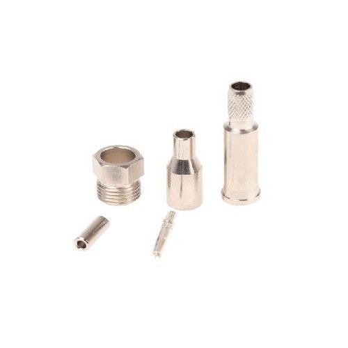
Flexible Mounting & TerminationChoose from panel mount, cable mount, or bulkhead options to suit your installation needs. With multiple termination stylescrimp, solder, or clampthese connectors can be easily incorporated into diverse coaxial systems for both new installations and upgrades.
Superior Performance & VersatilitySupporting a frequency range up to 11 GHz and maintaining impedance of 50 Ohm, these connectors offer low VSWR and outstanding contact and insulation resistance. Their customizable length, robust screw-lock coupling, and solid round pin ensure reliable performance in antennas, wireless systems, and laboratory testing.
FAQs of N Type Connector:
Q: How is the N Type Connector mounted for installation?
A: The N Type Connector can be mounted using panel mount, cable mount, or bulkhead configurations, providing flexibility for various RF system setups. Select the appropriate mounting style based on your application and installation requirements.
Q: What benefits does the threaded coupling mechanism offer?
A: The threaded 5/8-24 UNEF screw-lock coupling ensures a secure, vibration-resistant connection, preventing accidental disconnection and maintaining superior RF integrity in environments subject to physical stress or movement.
Q: When should I use a male (plug) versus a female (jack) version of the connector?
A: Choose the male (plug) or female (jack) version based on the mating connector in your system. Typically, cables use male connectors, while devices and panels are equipped with female jacks for reliable connectivity and compatibility.
Q: Where are N Type Connectors typically used?
A: These connectors are widely used in telecommunications, antenna systems, base stations, RF equipment, laboratory instruments, and wireless networks, where robust construction and low signal loss are essential for system performance.
Q: What process is recommended for terminating these connectors?
A: Termination can be achieved by crimping, soldering, or using a clamp, depending on the cable type and system requirements. Follow manufacturer guidelines for the specific termination process to ensure optimal signal transmission and mechanical stability.
Q: How does this connector ensure reliable RF performance?
A: With a VSWR of 1.3 (up to 3 GHz), low contact resistance, and high insulation resistance, the N Type Connector minimizes signal loss while delivering consistent, high-quality RF transmission across its specified frequency range.
Q: What features provide weatherproof and durable protection?
A: The nickel-plated brass housing, PTFE insulation, and robust threaded locking mechanism combine to offer excellent weatherproofing, corrosion resistance, and long-term reliability, even in harsh outdoor or industrial conditions.





 Send Inquiry
 Get Latest Price

