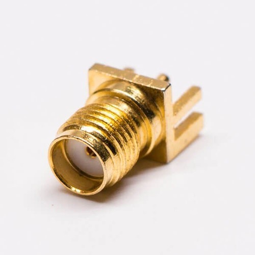
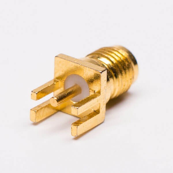
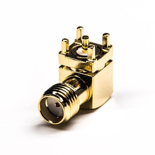
About SMA Connector Straight Female For Edge Mount
Techinial Datasheet:
Electrical Characteristics
- Impedance50 ohm
- Frequency Range: 0~3 GHz
- VSWR: Straight type 1.3max / R/A type 1.5max
- Dielectric Withstanding Voltage:1000 V rms min for RG142, RG405
750 V rms min. for RG316, RG402
500v rms min. for RG178 - Working Voltage: 500 V rms max. for RG142, RG405
375 V rms max. for RG316, RG402
170 V rms max. for RG178 - Center Contact Resistance 6.0 m (Milliohms max.)
- Outer Contact Resistance 2.0 m (Milliohms max.)
- Insultation Resistance 5 x 10 m (Megohms min.)
Mechanical Characteristics
- Coupling: 1/4-36 thread
- Contact Retention: 15 in-lbs min.
- Coupling nut torque: 30 in-lbs. min.
- Durability(mating) 500 cycles (For Beryllium Copper Contact)
Environmental Characteristics
- Environmental Characteristics: -65C ~ +165C
- Vibration: MIL-STD-202 Meth.204
- Corrosion resistance: MIL-STD-202 Meth. 101
Material:
| Part | Material | Finish |
| Body | BRASS | Au:1-3u" |
| insulator | TEFLON | NONE |
| Center Contact Pin | BRASS | Au:5u" |
High-Frequency Performance with Low VSWREngineered for demanding RF and microwave applications, this SMA connector maintains a low VSWR ( 1.3 up to 18 GHz) for minimal signal loss and reflection. Its gold-plated surfaces and PTFE insulation ensure optimal electrical values, making it a reliable choice for precision applications.
Durable Design and Reliable TerminationManufactured to MIL-STD-348A standards, this connector offers gold-over-nickel contact plating and robust brass construction, supporting over 500 mating cycles without performance loss. The solder termination style and threaded coupling provide a secure and long-lasting connection on PCB edges.
Easy Edge Mount InstallationDesigned specifically for PCB edge mounting, the right-angle form factor provides straightforward installation, even in compact devices. This makes it perfect for telecommunications equipment, laboratory instrumentation, and RF signal transmission systems where space and performance are critical.
FAQs of SMA Connector Straight Female For Edge Mount:
Q: How do I install the SMA Connector Straight Female for Edge Mount onto a PCB?
A: Align the connector at the PCB edge, ensuring the solder termination contacts the designated pads. Solder the connector securely in place as per standard PCB edge-mount procedures, taking care to avoid overheating the PTFE insulation.
Q: What are the main benefits of gold-plated contacts in this SMA connector?
A: Gold plating over nickel provides excellent conductivity, corrosion resistance, and enhances signal integrity, especially for high-frequency applications up to 18 GHz, ensuring long-term reliability and performance.
Q: Where can I use this SMA edge mount connector?
A: This connector is ideal for RF and microwave circuits, telecommunications devices, test equipment, and laboratory instrumentation requiring reliable coaxial connectivity on PCB edges.
Q: What frequencies is the connector suitable for?
A: The connector covers a frequency range from DC up to 18 GHz, making it suitable for a wide variety of high-frequency signal transmission applications.
Q: What makes the right-angle, edge-mount style advantageous?
A: The right-angle, edge-mount style allows the connector to be easily installed on PCB edges, optimizing space utilization and enabling straightforward routing of RF signals in compact device layouts.
Q: Is this connector RoHS and REACH compliant?
A: Yes, the SMA Connector Straight Female for Edge Mount meets RoHS and REACH environmental compliance standards, making it suitable for use in eco-conscious applications globally.






 Send Inquiry
 Get Latest Price

