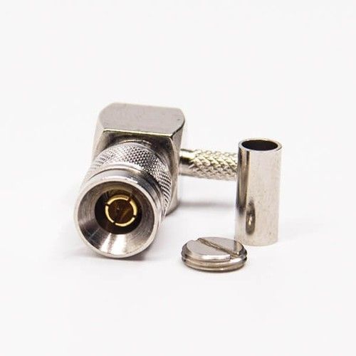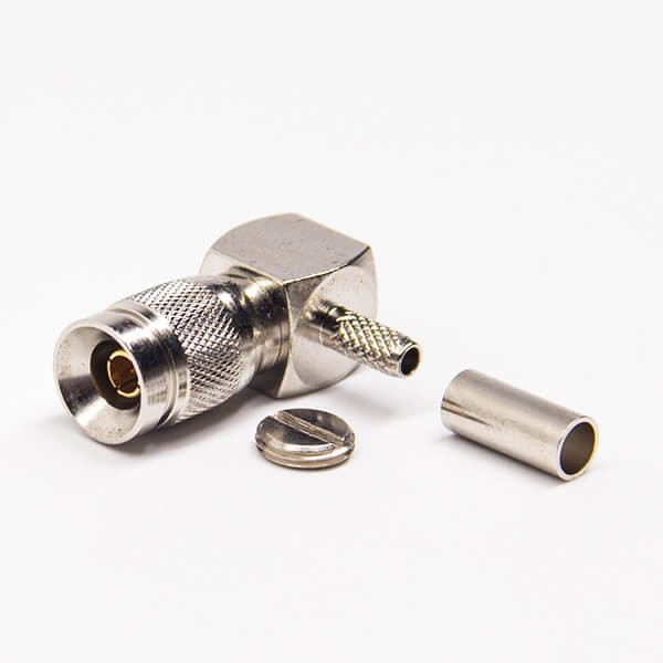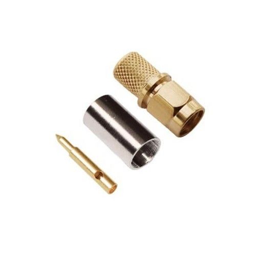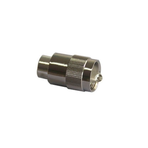
DIN 1.0/2.3 Connector Right Angle Male Crimp Type For Coaxial Connector About
Details - Impedance 50 ohm or 75 ohm
- Frequency Range: 0~4 GHz for 50 ohm, 0~2 GHz for 75 ohm
- VSWR: Straight type 1.3max / R/A type 1.5max
- Dielectric Withstanding Voltage: 750 V rms
- Working Voltage: 250 V rms
- Center Contact Resistance 6.0 m (Milliohms max.)
- Outer Contact Resistance 3.0 m (Milliohms max.)
- Insultation Resistance 10 m
High-Performance Signal TransmissionEngineered to support frequencies up to 4 GHz with an impedance of 50 Ohms, the DIN 1.0/2.3 connector ensures minimal signal loss and interference. Its gold-plated contacts maintain low contact resistance, making it ideal for applications where signal integrity is critical, such as RF circuits, test equipment, and wireless communications.
Durable and Reliable ConstructionManufactured from brass with nickel plating, coupled with PTFE insulation, this connector withstands harsh operating conditions. It boasts a mechanical durability of more than 500 mating cycles and a wide temperature range (-55C to +155C), making it suitable for both field and panel installations.
Easy Installation and Versatile UsageThe connector features a right angle geometry and push-pull coupling mechanism, simplifying integration into tight spaces. Its crimp/solder termination style ensures secure, stable connections for a variety of coaxial cables. Its compact size and compatibility with popular cable types enhance versatility across telecommunications, broadcasting, and microwave systems.
FAQs of DIN 1.0/2.3 Connector Right Angle Male Crimp Type For Coaxial Connector:
Q: How do I install the DIN 1.0/2.3 right angle male connector on coaxial cables?
A: Installation involves the crimp or solder termination method, supporting cables like RG-58 and RG-174. Carefully strip the cable, insert the conductor into the connector pin, and secure the assembly using an appropriate crimping tool or soldering equipment for reliable connection.
Q: What are the benefits of using this connector in RF and telecom applications?
A: Its low VSWR ( 1.15 up to 4 GHz), high insulation resistance (> 5000 M), gold-plated contacts, and robust mechanical design ensure superior signal transmission, reduced interference, and long-lasting durability in demanding environments, such as wireless and microwave communication.
Q: When should I choose the right angle version of the DIN 1.0/2.3 connector?
A: Opt for the right angle model when installation space is limited or when cables need to be routed neatly within equipment enclosures. The compact design allows for efficient cable management in densely populated PCBs or panels.
Q: Where is this connector typically used?
A: This connector is commonly utilized in RF circuits, telecommunications equipment, broadcasting, and test & measurement devices, especially where compact size, reliable signal transmission, and field termination are essential.
Q: What is the process for panel or PCB mounting?
A: For panel or PCB installation, the connectors right angle structure fits securely onto the board or chassis. Its push-pull coupling mechanism provides quick mating and de-mating, while crimp or solder termination ensures a stable and solid electrical contact.
Q: What standards and compliances does the connector adhere to?
A: The connector complies with DIN 47297 and IEC 61169-29 standards, ensuring industry-accepted mechanical and electrical performance. It is also RoHS compliant, affirming its suitability for environmentally conscious applications.
Q: What is the expected lifespan and durability of the connector?
A: The DIN 1.0/2.3 connector offers mechanical durability of at least 500 mating cycles, high tensile strength, and operates reliably across a wide temperature range, making it suitable for repeated use and harsh environmental conditions.