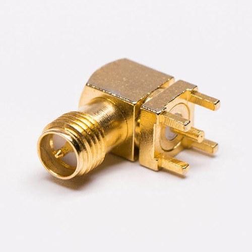
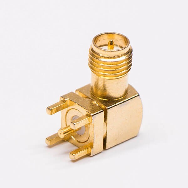
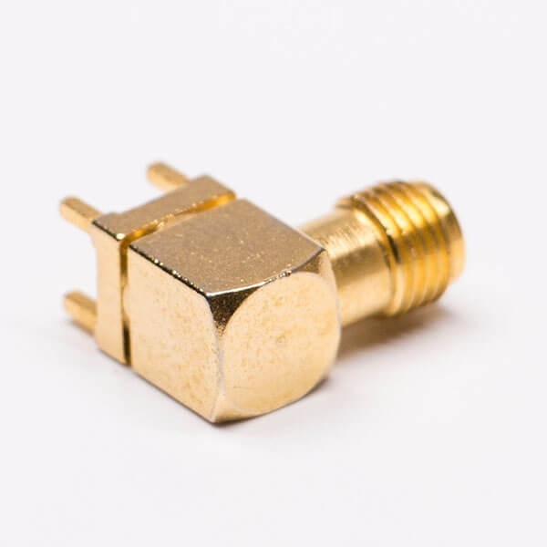
About RP-SMA Jack Connector Angled Gold Plated For PCB
Electrical Characteristics
50 ohm
1.3max / R/Atype 1.5max
6.0 m (Milliohms max.)
2.0 m (Milliohms max.)
5 x 10 m(Megohms min.)
Mechanical Characteristics
500 cycles(For Beryllium Copper Contact)
Environmental Characteristics
Corrosion resistance: MIL-STD-202 Meth. 101
Material:
| Part | Material | Finish |
| Body | Brass | NI 80-120u" |
| Insulator | TEFLON | White |
| Center Contact Pin | Phosphor | Au:3u" |
Reliable, High-Frequency PerformanceDesigned for RF signal integrity, this RP-SMA jack connector offers low insertion loss and excellent impedance matching up to DC to 6 GHz. Its gold-plated finish over a brass core reduces signal degradation and ensures consistent quality across applications such as antenna feeds and communication devices.
Durable Construction and ComplianceBuilt from gold-plated brass with a PTFE insulator, the connector supports operation between -65C and +165C, exhibits high insulation resistance ( 5000 M), and boasts a flammability rating of UL 94V-0. Coupled with RoHS environmental compliance, this ensures both safety and performance in demanding electronic environments.
Easy Installation for PCB ApplicationsFeaturing a right-angle, through-hole design tailored for PCB mounting, this connector simplifies board integration. Its threaded coupling mechanism ensures a secure RF connection while the compact footprint allows for versatile placement on standard PCB layouts in wireless modules, test equipment, and communication systems.
FAQs of RP-SMA Jack Connector Angled Gold Plated For PCB:
Q: How do I mount the RP-SMA Jack Connector onto a PCB?
A: The connector is designed for through-hole, right-angle installation. Simply align the pins with the corresponding PCB holes, solder them in place, and secure the threaded coupling if attaching antennas or modules. Ensure you follow the recommended pad design from the datasheet for optimal mechanical strength.
Q: What benefits does the gold plating offer on this RP-SMA connector?
A: Gold plating over nickel enhances conductivity, prevents corrosion, and reduces signal loss. This ensures reliable performance even with multiple mating cycles and in environments exposed to moisture or oxidation.
Q: What is the typical application for this RP-SMA Jack Connector?
A: It is commonly used in RF signal and antenna connections, particularly in PCB wireless modules, communication devices, and test equipment. Its durable and compact design makes it suitable for both commercial and industrial electronic assemblies.
Q: What is the operating and storage temperature range for this connector?
A: The RP-SMA Jack Connector can operate or be stored in temperatures ranging from -65C to +165C, making it suitable for both indoor and outdoor environments with varying thermal conditions.
Q: Where is this connector typically implemented?
A: It is designed exclusively for PCB mounting. Youll find it in wireless modules, communication devices requiring RF connectivity, and lab test equipment, all of which demand stable and durable RF connections.
Q: What process ensures a secure RF connection with this RP-SMA jack?
A: The connector uses a threaded coupling (screwed) locking mechanism, which helps maintain a stable connection and minimizes signal losses due to mechanical vibrations or accidental pulls.
Q: When should I use a reverse polarity (RP) SMA connector?
A: Reverse polarity SMA connectors are used when a device or module requires RP compatibilitycommonly as an industry safeguard to prevent accidental connection with standard SMA cables, ensuring correct signal routing in compliant equipment.





 Send Inquiry
 Get Latest Price

